- 您现在的位置:买卖IC网 > Sheet目录1995 > DS4412U+ (Maxim Integrated Products)IC DAC DUAL CH I2C ADJ 8-USOP
DS4412
Dual-Channel, I2C Adjustable
Sink/Source Current DAC
_______________________________________________________________________________________
3
Note 1: All voltages with respect to ground, currents entering the IC are specified positive and currents exiting the IC are negative.
Note 2: Supply current specified with all outputs set to zero current setting with all inputs driven to well-defined logic levels. SDA and
SCL are connected to VCC. Excludes current through RFS resistors (IRFS). Total current includes ICC + 2.5 x (IRFS0 + IRFS0).
Note 3: The output voltage range must be satisfied to ensure the device meets its accuracy and linearity specifications.
Note 4: Input resistors RFS must be between 2.25k
Ω and 9.0kΩ to ensure the device meets its accuracy and linearity specifications.
Note 5: Temperature drift excludes drift caused by external resistor.
Note 6: Differential linearity is defined as the difference between the expected incremental current increase with respect to position
and the actual increase. The expected incremental increase is the full-scale range divided by 15.
Note 7: Integral linearity is defined as the difference between the expected value as a function of the setting and the actual value.
The expected value is a straight line between the zero and the full-scale values proportional to the setting.
Note 8: Timing shown is for fast-mode (400kHz) operation. This device is also backward compatible with I2C standard-mode timing.
Note 9: CB—total capacitance of one bus line in pF.
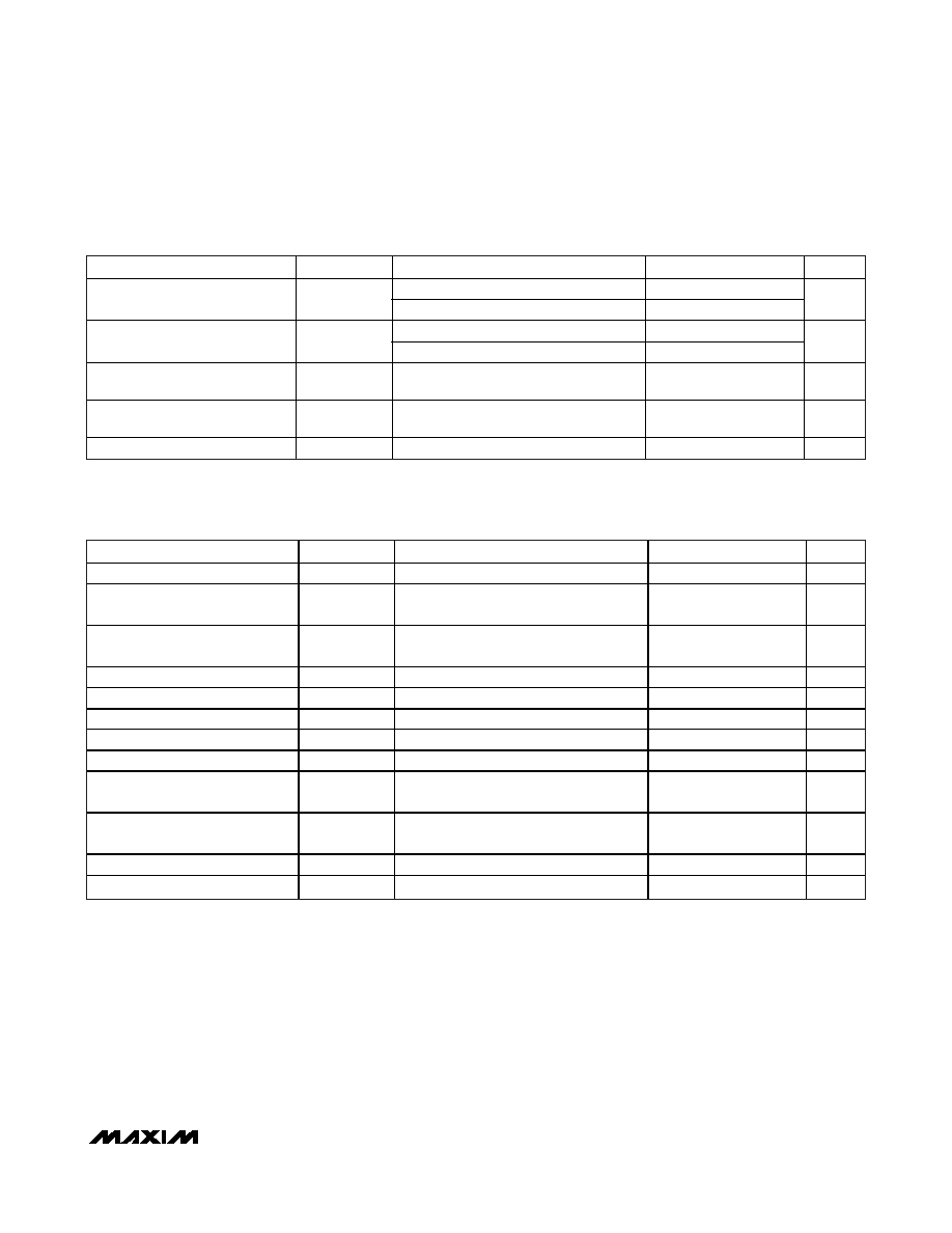
OUTPUT CURRENT CHARACTERISTICS (continued)
(VCC = +2.7V to +5.5V, TA = -40°C to +85°C.)
PARAMETER
SYMBOL
CONDITIONS
MIN
TYP
MAX
UNITS
DC source
+0.36
Output-Current Variation due to
Power-Supply Change
DC sink
+0.12
%/V
DC source, VOUT measured at 1.2V
-0.02
Output-Current Variation due to
Output Voltage Change
DC sink, VOUT measured at 1.2V
+0.12
%/V
Output Leakage Current at Zero
Current Setting
IZERO
-1
+1
μA
Output-Current Differential
Linearity
DNL
(Note 6)
0.5
LSB
Output-Current Integral Linearity
INL
(Note 7)
1
LSB
I2C AC ELECTRICAL CHARACTERISTICS
(VCC = +2.7V to +5.5V, TA = -40°C to +85°C.)
PARAMETER
SYMBOL
CONDITIONS
MIN
TYP
MAX
UNITS
SCL Clock Frequency
fSCL
(Note 8)
0
400
kHz
Bus Free Time Between STOP
and START Conditions
tBUF
1.3
s
Hold Time (Repeated) START
Condition
tHD:STA
0.6
s
Low Period of SCL
tLOW
1.3
s
High Period of SCL
tHIGH
0.6
s
Data Hold Time
tDH:DAT
0
0.9
s
Data Setup Time
tSU:DAT
100
ns
START Setup Time
tSU:STA
0.6
s
SDA and SCL Rise Time
tR
(Note 9)
20 +
0.1CB
300
ns
SDA and SCL Fall Time
tF
(Note 9)
20 +
0.1CB
300
ns
STOP Setup Time
tSU:STO
0.6
s
SDA and SCL Capacitive Loading
CB
(Note 9)
400
pF
发布紧急采购,3分钟左右您将得到回复。
相关PDF资料
DS4424N+
IC DAC 7BIT 4CH 5.5V 14-TDFN
DS4425BN+
IC OSC CLOCK 425MHZ 10-LCCC
DS4426T+T&R
IC DAC I2C-MARGINING 4CH 28-TQFN
DS4432U+
IC DAC 7BIT 2CH 5.5V 8-MSOP
DS4625P+150/200
IC OSC CLOCK 200MHZ 10-LCCC
DS4M133D+33
IC OSC CLOCK 133.33MHZ 10-LCCC
DS8005-RRX+
SMART CARD AFE DUAL 28SOIC
DSD1792DB
IC 24BIT STEREO AUD DAC 28-SSOP
相关代理商/技术参数
DS4412U+T&R
制造商:Maxim Integrated Products 功能描述:DAC 2CH 4BIT 8USOP - Tape and Reel 制造商:Maxim Integrated Products 功能描述:IC DAC DUAL CH I2C ADJ 8-USOP
DS4412U+T&R
功能描述:数模转换器- DAC 2 Ch I2C Adj Sink/Source Current RoHS:否 制造商:Texas Instruments 转换器数量:1 DAC 输出端数量:1 转换速率:2 MSPs 分辨率:16 bit 接口类型:QSPI, SPI, Serial (3-Wire, Microwire) 稳定时间:1 us 最大工作温度:+ 85 C 安装风格:SMD/SMT 封装 / 箱体:SOIC-14 封装:Tube
DS4412U+TR
制造商:MAXIM 制造商全称:Maxim Integrated Products 功能描述:Dual-Channel, I2C Adjustable Sink/Source Current DAC
DS4412UR
制造商:MAXIM 制造商全称:Maxim Integrated Products 功能描述:Dual-Channel, I2C Adjustable Sink/Source Current DAC
DS4412UT
制造商:MAXIM 制造商全称:Maxim Integrated Products 功能描述:Dual-Channel, I2C Adjustable Sink/Source Current DAC
DS441405-BA
功能描述:CAP FILM 4UF 440VAC QC TERM RoHS:是 类别:电容器 >> 薄膜 系列:PMF 特色产品:ECW-H(C) Series Film Capacitors 标准包装:100 系列:ECW-H(C) 电容:0.33µF 额定电压 - AC:- 额定电压 - DC:630V 电介质材料:聚丙烯,金属化 容差:±3% ESR(等效串联电阻):- 工作温度:-40°C ~ 105°C 安装类型:通孔 封装/外壳:径向 尺寸/尺寸:0.815" L x 0.579" W(20.70mm x 14.70mm) 高度 - 座高(最大):1.028"(26.10mm) 端子:PC 引脚 引线间隔:0.394"(10.00mm) 特点:高频和高稳定性 应用:- 包装:散装 其它名称:ECWH6334HCBP15432
DS4414FP00K
制造商:Thomas & Betts 功能描述:400A,CON,3P4W,MG,414,3P600V,CC
DS4414FR000
制造商:Thomas & Betts 功能描述:400A,REC,3P4W,MG,414,3P600V